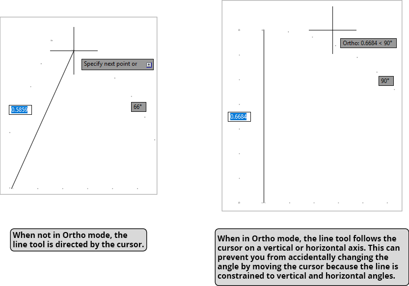
Ortho is short for orthographic. In orthographic drawing, all lines are either vertical or horizontal. When using a command, Ortho Tracking constricts all angles to 0° or 90° horizontal or vertical angles. When using the Line tool, the line will only follow a vertical or horizontal path rather than following the cursor as it would with Polar Tracking. This means that the line will go vertically or horizontally in the general direction of the cursor so you won’t have to move the cursor as much and drawing will be a lot faster. It also can prevent you from accidentally moving the cursor and changing the angle because the line stays vertical or horizontal. Most lines in drafting are vertical or horizontal, so Ortho Tracking is a very effective way to speed the drawing process. You can easily switch between Ortho and Polar Tracking when necessary by clicking in the Status Bar or pressing F8 or F10, without interrupting any command you may be currently using.
This exercise is excerpted from Noble Desktop’s past AutoCAD training materials and is compatible with Photoshop updates through 2020. To learn current skills in AutoCAD, check out AutoCAD Bootcamp and AutoCAD classes in NYC and live online.
Note: These materials are provided to give prospective students a sense of how we structure our class exercises and supplementary materials. During the course, you will get access to the accompanying class files, live instructor demonstrations, and hands-on instruction.
Topics covered in this AutoCAD tutorial:
Ortho tracking, Additional polar angles
Ortho Tracking (F8 in the Status Bar)
Ortho is short for orthographic. In orthographic drawing, all lines are either vertical or horizontal. When using a command, Ortho Tracking constricts all angles to 0˚ or 90˚ horizontal or vertical angles. When using the Line tool  , the line will only follow a vertical or horizontal path rather than following the cursor as it would with Polar Tracking. This means that the line will go vertically or horizontally in the general direction of the cursor so you won’t have to move the cursor as much and drawing will be a lot faster. It also can prevent you from accidentally moving the cursor and changing the angle because the line stays vertical or horizontal. Most lines in drafting are vertical or horizontal, so Ortho Tracking is a very effective way to speed the drawing process. You can easily switch between Ortho and Polar Tracking when necessary by clicking in the Status Bar or pressing F8 or F10, without interrupting any command you may be currently using.
Additional Polar Angles
Assigning incremental Polar Tracking angles was covered in Chapter 2. However, you can also assign a custom angle to create a tracking line. In AutoCAD, this is refereed to as an Additional Angle. Additional Angles can be entered by expanding the Polar Tracking menu in the Status Bar and selecting Tracking Settings. When the Tracking Settings dialog box appears, click the New button to add Additional Angles. There is also an Additional Angles check box so you can deactivate them when not in use without having to delete them and reenter them when needed. You won’t want to have Additional Angles active when they’re not needed so you won’t accidentally snap to the wrong tracking line.
![]()
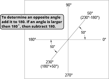
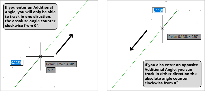
Additional angles are absolute as opposed to relative, so whatever angle you enter will only create one tracking line of that angle counter clockwise from the horizon line at 0˚. Because you will only get a tracking line in one direction with your cursor, it’s usually a good idea to also enter the opposite angle so you can track in either direction when you pull the cursor. To determine the opposite angle add it to 180. So, if the Additional Angle is 50˚ the opposite angle would be 230˚, which is 50+180. If you enter an Additional Angle that’s larger then 180˚, then subtract 180. So if you enter an angle of 230˚, the opposite angle is 230-180, or 50˚. You can also sketch a diagram on a piece of paper similar to the one below to determine the opposite angle.