Create a Drawing in AutoCAD based on an Architectural template and explore various elements and settings saved to the template.
This exercise is excerpted from Noble Desktop’s past AutoCAD training materials and is compatible with Photoshop updates through 2020. To learn current skills in AutoCAD, check out AutoCAD Bootcamp and AutoCAD classes in NYC and live online.
Note: These materials are provided to give prospective students a sense of how we structure our class exercises and supplementary materials. During the course, you will get access to the accompanying class files, live instructor demonstrations, and hands-on instruction.
Topics covered in this AutoCAD tutorial:
Drawing template files (.dwt), Creating a file based on a template
Exercise Preview
Exercise Overview
In this exercise you will make a Drawing based on an Architectural template and explore various elements and settings saved to the template.
Drawing Template Files (.dwt)
In order to create new Drawing files (.dwg) ![]() in AutoCAD with New command (Ctrl–N), you must choose a preexisting Drawing Template file (.dwt)
in AutoCAD with New command (Ctrl–N), you must choose a preexisting Drawing Template file (.dwt) ![]() to base the drawing on. Templates are used to save custom default settings, units, scales, layers, styles, attached blocks, and layouts. Anything that can be saved in a drawing file
to base the drawing on. Templates are used to save custom default settings, units, scales, layers, styles, attached blocks, and layouts. Anything that can be saved in a drawing file ![]() can be saved in a template file
can be saved in a template file ![]() . The purpose of a template is to save everything you would want to be set up in every new drawing. This will save you from having to change settings for every new drawing. You can make different templates for different kinds of drawings using different units, like architectural, civil, or mechanical drawings using metric or imperial measurements.
. The purpose of a template is to save everything you would want to be set up in every new drawing. This will save you from having to change settings for every new drawing. You can make different templates for different kinds of drawings using different units, like architectural, civil, or mechanical drawings using metric or imperial measurements.
Once a Template file is created, it cannot be opened on its own. It only exists to create Drawing files. Because Template files generate Drawing files and can’t be opened on their own by default, it’s very unlikely that you will accidentally save over your Template with a working document, which is the main reason Template files are used.
To Create a Drawing File from a Template
Choose a template file
 with the New command (Ctrl–N or File > New).
A new Drawing file (.dwg)
 is created. The file won’t have the same name as the Template. It’s always named Drawing1.dwg, or a different number depending on how many new drawings you’ve created since AutoCAD was opened.
Because the new file is a different type and name from the Template, once you’ve started drawing and save the file, it will remain a .dwg
by default, and NOT a .dwt, which will prevent you from accidentally saving over the original Template file.
Creating a File Based on a Template
Start the New command (File > New or Ctrl–N). You will see the Select Template dialog box. Note that the icons for .dwt files
are red as opposed to the yellow and blue icons for a .dwg file . This will help you realize if you’ve mistakenly selected File > Open instead of File > New or vice versa. By default, the New command will always navigate to the folder of Template files that come with AutoCAD. You will learn how to change the default folder in the next exercise. For now, navigate to the student file folder and select the Template Architectural-Imperial.dwt. Double–click on Template or click the Open button. A new .dwg Drawing file named Drawing.dwg will be created. The name will also include a number based on how many new drawings were created since AutoCAD was opened.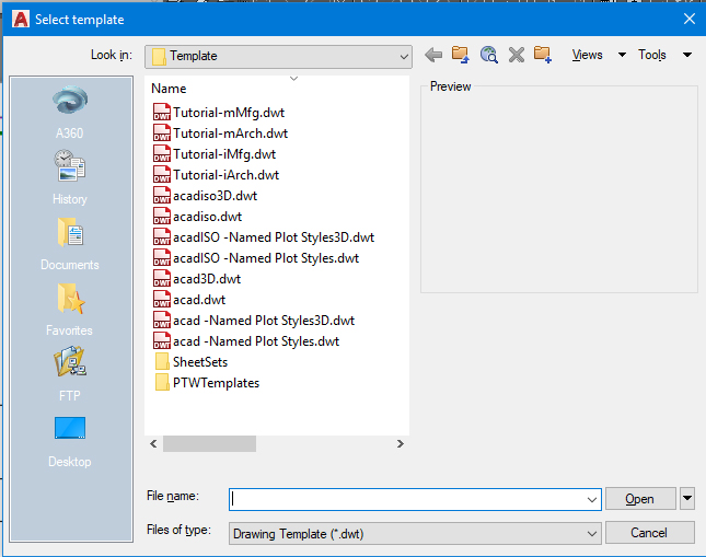
Start the Save As command (Ctrl–Shift–S or File > Save As). You will see that the file type is .dwg, not .dwt. Name the file End Table.dwg and click Save.
Start the Units command or select Units from the Format menu. The Drawing Units dialog box will appear, as shown below.
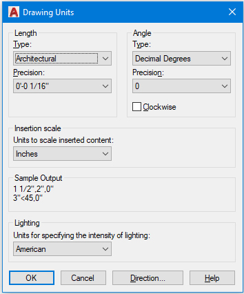
Note that the units are set to inches and the length type is set to Architectural, meaning feet will be entered with the
'mark, so you would enter a distance of 6 feet and 5 inches as 6'5.Expand the drop-down menu in the Layer panel or the Layer toolbar. This menu—shown in the screenshot below—is called the Layer Control. Note how the names of the layers refer to the types of objects you might find in an architectural drawing like walls, doors, windows, and furniture. You would not find objects like these in drawings of circuit boards and car parts! The color swatches show what colors the objects on those layers will be.
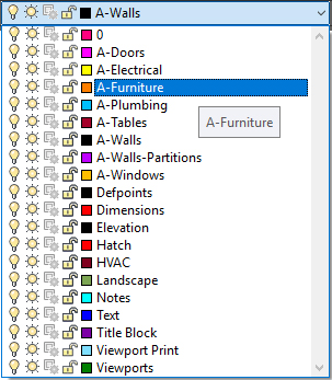
Click on the layer A-Furniture. This will make A-Furniture the current layer so that new objects will be created on the A-Furniture layer and will have the properties assigned to that layer. Since you will be drawing an end table, you will want it to be on the A-Furniture layer.
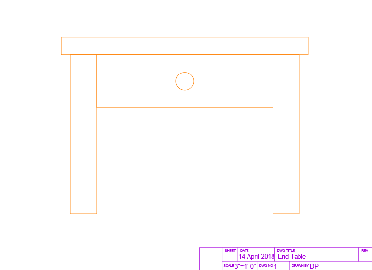
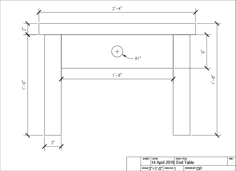
Now you will draw an end table based on the dimensions given in the diagram below. Note the architectural units. The diagram is also annotated in an architectural dimensioning style.
Start the Rectangle command
 to make the table top. Click anywhere to establish the start point of the rectangle, then in architectural units, type 2’’’4, 2 for the X and Y values.
To make the drawer, press Enter to restart the Rectangle command
. Click anywhere for the start point and enter 1’’’8, 6 for the dimensions.Now you will draw the legs. Draw a rectangle at another random start point with the dimensions 3
"x1'8. Use the Copy command to make a copy of the rectangle and place it anywhere.Use the Move command
 to assemble the table by attaching the other rectangles to the drawer as shown below.
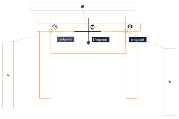
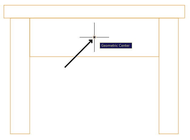
For the last step, use the Circle tool
 to make the drawer knob by using the Geometric Center snap to place the center point of the circle at the center of the drawer rectangle. Remember that the cursor must touch the edge of the rectangle to reveal its geometric center. Enter a radius of 1.
TIP: Place the center point of the circle at the geometric center of the rectangle, as shown in the screenshot below:
The end table is complete! Close and save the file.